Wireless Welding Machine
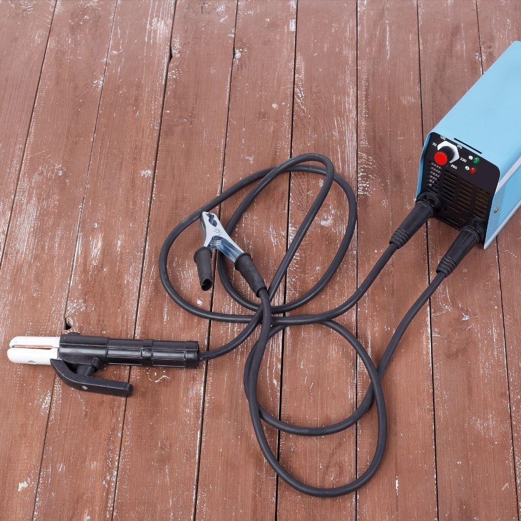
Systems referred to as wireless in industrial welding applications are considered solutions developed to reduce cable density in the working area. Energy transmission, as in traditional welding technologies, is provided through physical connections. The distinguishing factor lies in portability and adaptability to field conditions.
Compact structure and integrated power regulation shorten setup time and enhance operator mobility. This configuration offers a usage model that supports operational efficiency, particularly in field-based and mobile production processes.
Instead of conventional welding machine cables, shorter connections, integrated current-carrying structures, or mobile power units are emphasized in these systems. The design approach aims to minimize cable clutter and allow operators to move more freely within the workspace. A durable outer housing resists impact and environmental effects, providing safe use in field conditions. The portable structure also offers advantages during maintenance and transportation.
Key features highlighted in welding systems evaluated under the wireless structure approach include:
- Compact and lightweight design
- Power regulation suitable for mobile use
- Integrated connections reducing cable requirements
- Fast setup and practical transportation in the field
- Compatibility with off-site applications
The concept of wireless does not imply operation independent of technical infrastructure. Energy transmission and welding performance are evaluated through the system’s internal components. During selection, usage area, operating duration, and technical requirements should be considered together.
How to Connect a Welding Machine Cable?
Ensuring proper cable connection in welding equipment is important for users seeking safe and efficient operation. Following the correct sequence during the connection process contributes to equipment protection and balanced welding performance. Before application, the machine must be turned off and disconnected from the power source. Clean and undamaged cable ends directly affect contact quality.
During connection, the cable must be properly positioned in the corresponding output on the machine. Polarity arrangement is determined according to electrode type and welding technique. When proper tightening is applied, contact losses are prevented and current transmission becomes stable. Since connection points may vary across different welding machines, actions should align with the manufacturer’s technical structure.
The basic steps followed during cable connection are as follows:
- Completely turning off the machine’s power supply
- Checking cable ends and connection points
- Placing the cable into the output suitable for correct polarity
- Ensuring the connection head is tightened and contact surfaces fit properly
- Attaching the electrode holder or grounding clamp to the appropriate point
After installation, a short test run is recommended. If no overheating, loosening, or contact issues are observed, operation can proceed safely. A proper connection setup supports long-term system stability.
Inverter Welding Machine Cable
Cables used in modern welding systems are designed to comply with the high-frequency current structure required by inverter technology. In these systems, balanced and loss-free energy transmission through the cable plays a decisive role in maintaining welding performance.
Cable cross-section, conductor density, and insulation structure directly influence welding stability. Using an unsuitable cable may lead to performance loss and connection failures.
Cables preferred for inverter systems provide mobility thanks to their flexible structure. Resistance to bending becomes important in applications requiring work in confined spaces. A heat-resistant outer sheath ensures safe use during intensive operation.
Selecting a cable with the correct technical specifications increases equipment compatibility and offers long-term usage advantages. This structure enables the system to establish a durable operating order.
Key points highlighted in cable selection for inverter welding machines include:
- Cross-sectional area suitable for current capacity
- Flexible, crack-resistant insulation structure
- Sheathing resistant to heat and environmental effects
- Lightweight and portable usage advantage
- Technical compatibility with inverter systems
During the selection process, not only length or cost but also operating conditions should be evaluated. Proper cable use supports stable operation of inverter welding systems and contributes to continuity in welding quality.